1. Introduction
Electroplating quality is highly dependent on the stability of DC power output. Among all power-related influencing factors, ripple current is one of the most overlooked yet critical issues that determine coating uniformity, surface smoothness, metal adhesion, and final corrosion resistance in all electroplating processes.
Excessive ripple current in electroplating DC power supplies frequently causes typical production defects, including uneven plating thickness, micro pinholes, edge burrs, foggy surfaces, and poor layer adhesion. These problems directly increase scrap rates, rework costs, and overall production losses for electroplating factories.
Most traditional rectifiers on the market generate noticeable ripple during operation. Without targeted optimization, long-term high-ripple operation will continuously undermine product consistency and brand competitiveness.
This article systematically explains what electroplating ripple current is, analyzes its core causes and production hazards, and summarizes eight practical, industry-proven methods to effectively reduce ripple current for electroplating production lines. Whether you operate decorative plating, hard plating, or precision alloy plating lines, these solutions can help you stabilize DC power output and upgrade overall production quality.
If you are plagued by unstable electroplating quality caused by power ripple, contact our professional engineer team to get a free customized power parameter optimization scheme.
2. What Is Ripple Current in Electroplating DC Power Supplies?
2.1 Basic Definition of Power Ripple Current
Ripple current refers to the periodic AC fluctuation signal superimposed on the pure DC output of an electroplating rectifier power supply. All switching DC power supplies produce certain degrees of ripple during rectification, filtering, and high-frequency switching operations.
Unlike general industrial DC power, electroplating processes require extremely smooth current and voltage output. Even tiny current fluctuations will change the ion migration speed in the plating solution, resulting in inconsistent metal deposition effects.
2.2 Acceptable Ripple Standards for Different Electroplating Processes
Different plating scenarios have completely different ripple tolerance thresholds. The higher the precision requirement, the lower the allowable ripple rate:
- Ordinary decorative plating: Allowable ripple rate below 3%–5%
- Nickel and chromium hard plating: Require ripple rate below 1%–2%
- Precious metal plating (gold, silver, alloy): Require ultra-low ripple below 0.5%
- Aerospace and high-precision component plating: Need strictly controlled ultra-stable ripple output
Once the actual ripple exceeds the process standard, plating defects will appear in batches within a short production cycle.
| Plating Process Type | Allowable Maximum Ripple Rate | Core Quality Requirement | Typical Application Scenarios |
| Ordinary decorative plating | 3%–5% | Basic uniform appearance | Plastic electroplating, daily hardware decorative coating |
| Nickel & chromium hard functional plating | 1%–2% | High hardness, wear resistance | Automotive parts, mold hard chrome plating |
| Precious metal plating (Au/Ag/alloy) | ≤0.5% | Ultra-smooth surface, compact coating | Electronic contacts, jewelry plating |
| Aerospace high-precision component plating | <0.3% | Zero pinhole, long anti-corrosion life | Aviation connectors, precision sensor parts |
Table 1: Allowable Ripple Rate Standard for Different Electroplating Processes
3. Harms of Excessive Ripple Current in Electroplating Production
3.1 Damaged Coating Uniformity and Surface Finish
High ripple current triggers unstable instantaneous current density on the workpiece surface during electroplating. Metal ions deposit unevenly, resulting in inconsistent plating thickness, fuzzy surfaces, granular protrusions, and micro cracks. For high-standard decorative and functional plating, these ripple-induced defects directly lead to unqualified appearance inspection and batch product rejection.
3.2 Reduced Metal Adhesion and Corrosion Resistance
Unstable current will disorder the metal crystal growth structure during electroplating. The formed coating is loose in texture, poor in compactness, and prone to peeling, blistering, and falling off. Meanwhile, the uncompact protective layer greatly reduces the product’s anti-rust and anti-corrosion performance, shortening the service life of finished parts.
3.3 Higher Scrap Rate and Rising Operating Costs
Unqualified products caused by ripple current require repeated rework or direct scrapping, which wastes plating solution, labor, and time costs. Long-term unstable quality will also lead to delayed delivery and customer complaints, bringing invisible losses to factory reputation.
3.4 Shortened Service Life of Equipment and Fixtures
Continuous high-frequency current impact will accelerate the aging of plating fixtures, conductive rods, and power supply internal modules. Frequent equipment failure and maintenance will further affect production continuity and increase after-sales maintenance costs.
4. Core Causes of High Ripple Current in Electroplating DC Power Supplies
4.1 Defects in Rectifier Module and Filter Design
Most low-cost traditional electroplating rectifiers adopt simple half-bridge or full-bridge IGBT structures with basic filter circuits. These outdated designs cannot effectively suppress high-frequency switching ripple current, resulting in severe DC output fluctuations that fail to meet precision electroplating process requirements.
4.2 Aging of Power Devices and Component Attenuation
After long-term high-load operation, internal filter capacitors will experience capacity attenuation, ESR increase, and aging failure. Meanwhile, worn IGBT switching modules generate larger switching loss and current jitter, which directly elevates the overall ripple current level of electroplating DC power supplies.
4.3 Unstable Grid Voltage and Mismatched Line Impedance
Fluctuating factory grid voltage, long transmission lines, and unreasonable wiring layout will cause line impedance mismatch. External grid interference will be superimposed on DC output, forming additional low-frequency ripple and affecting power supply stability.
4.4 Unreasonable Current and Voltage Parameter Settings
Blindly increasing current density, frequent voltage adjustment, and long-term overload operation will make the power supply work in an unstable switching state, aggravating ripple fluctuation and causing continuous quality problems.
5. 8 Practical Methods to Reduce Electroplating Power Ripple Current
5.1 Upgrade to High-Precision Low-Ripple Rectifier Equipment
Traditional IGBT electroplating DC power supplies generally maintain a ripple rate of 2%–5%, which is unable to support high-precision plating production. Upgrading to SiC/GaN wide bandgap device power supplies can greatly optimize switching frequency and output stability. SiC modules feature lower switching loss, faster response, and more consistent current output, effectively suppressing high-frequency ripple current from the source.
5.2 Optimize Power Supply Filter Circuit Configuration
Reasonably upgrading multi-stage filter circuits and equipping high-quality filter capacitors and inductors can eliminate high-frequency clutter in DC output. Professional multi-stage filtering is one of the most cost-effective methods to smooth current fluctuations and lower the overall ripple current amplitude of electroplating power supplies.
5.3 Replace Aging Capacitors and Power Modules Regularly
Establishing regular maintenance cycles for electroplating DC power supplies is essential for stable operation. Timely replacement of aging filter capacitors, damaged rectifier bridges, and worn switching modules can avoid ripple current surge caused by component performance degradation.
5.4 Adopt Water-Cooled Heat Dissipation to Stabilize Power Output
Long-term high-temperature operation causes power device parameter drift and current instability, which directly increases ripple current. Water-cooled heat dissipation enables constant-temperature operation for high-current electroplating rectifiers, eliminating ripple fluctuation caused by overheating and ensuring long-term stable DC power output.
5.5 Optimize Working Current and Voltage Parameters
Setting current and voltage values strictly in accordance with actual plating process standards, avoiding long-term overload operation and sudden frequent adjustments can stabilize power supply operating status. Steady operating parameters effectively reduce power supply switching jitter and control ripple current within the ideal process range.
5.6 Optimize Workshop Power Wiring and Reduce Line Interference
Excessively long power transmission lines and unreasonable wiring layouts cause line impedance mismatch and electromagnetic interference, which induce extraripple current. Optimizing workshop wiring paths and shortening transmission lines can effectively reduce line interference and purify DC power output.
5.7 Adopt Pulse-Superimposed DC Power Supply Mode
The Pulse-DC composite output mode balances surface current density distribution, inhibits plating solution ion concentration polarization, and delivers excellent ripple current reduction. This optimized power mode also significantly improves coating compactness and uniformity for high-end electroplating processes.
5.8 Configure Independent Voltage Stabilization Equipment for Plating Workshops
Factory grid voltage fluctuation is a major external cause of unstableripple current. Installing independent voltage stabilizers and anti-interference equipment for electroplating production lines can isolate grid interference and provide pure, stable input voltage for rectifiers to maintain low-ripple DC output.
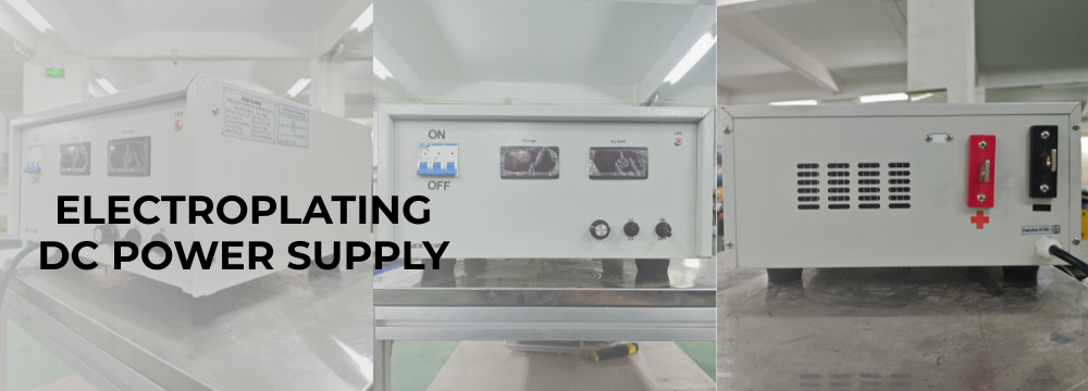
YIBENYUAN low-ripple electroplating DC power supply can strictly control the ripple rate within 0.5%, fully meeting the requirements of precision gold plating, nickel plating and alloy plating processes. Download our electroplating power parameter optimization manual to get professional ripple reduction operation guidelines for free.
6. Traditional Power Supply vs YIBENYUAN Low-Ripple Electroplating Power Supply
6.1 Ripple Output Data Comparison
Traditional ordinary electroplating rectifiers feature a ripple current rate of 2%–5%, accompanied by obvious current jitter during high-current operation. YIBENYUAN upgraded SiC low-ripple electroplating power supplies stably control ripple current below 0.5%, achieving ultra-smooth DC output and completely eliminating microscopic plating defects triggered by current fluctuation.
6.2 Production Yield and Quality Improvement
Factories using YIBENYUAN low-ripple power supplies have achieved significant improvements in coating uniformity, surface finish and adhesion. The product scrap rate caused by power instability is reduced by more than 80%, and the overall qualified rate of finished products is greatly improved.
6.3 Long-Term Stability and Cost Performance
Equipped with SiC high-efficiency devices and water-cooled constant temperature heat dissipation structure, YIBENYUAN electroplating power supplies feature low loss, low heat generation and long service life. Stable low-ripple operation reduces maintenance frequency and rework costs, bringing long-term energy-saving and stable production benefits for enterprises.
7. Practical Application Case: Precision Electroplating Factory Ripple Reduction Upgrade
A European precision hardware electroplating factory has long faced unstable nickel plating surfaces and coating peeling issues. After professional inspection, the core root cause was excessive ripple current generated by outdated IGBT rectifiers, which failed to meet high-precision plating quality standards.
The factory adopted YIBENYUAN customized low-ripple water-cooled electroplating DC power supply for renovation. After the upgrade, the overall ripple current rate was steadily controlled below 0.45%. The coating uniformity and surface finish were significantly improved, the product scrap rate dropped from 7.2% to 0.8%, and overall production qualification rate achieved a substantial upgrade.
Want to know the exact ripple reduction effect and cost-saving data of power supply transformation? Submit your workshop process parameters, and our engineer team will provide you with a targeted one-to-one transformation solution.
| Production Index | Before Renovation (Old IGBT Rectifier) | After YIBENYUAN Low-Ripple Power Upgrade | Improvement Range |
| Actual output ripple rate | 2.8%–3.6% | Stable 0.42%–0.45% | Ripple reduced over 87% |
| Nickel plating product scrap rate | 7.2% | 0.8% | Scrap rate cut 88% |
| Average daily rework cost | €328 | €41 | Daily loss reduced 87.5% |
| Power supply monthly maintenance times | 4–5 times | 1 time | Maintenance frequency down 75% |
| Salt spray test qualified ratio of finished parts | 82% | 90% | Pass rate increased 17% |
Table 2: Factory Before & After Renovation Data Contrast
8. Frequently Asked Questions
Q1: What is the best ripple current range for precision electroplating?
For standard precision electroplating, the ripple rate should be controlled below 1%. For precious metal plating and aerospace component plating, the optimal ripple range is within 0.5% to ensure ultra-high coating uniformity and compactness.
Q2: Can high ripple current cause electroplating layer peeling?
Yes. Excessive ripple will lead to disordered crystal growth and loose coating structure, resulting in insufficient adhesion. In severe cases, the plating layer will peel off, blister or fall off after a short period of use.
Q3: Is it necessary to replace the power supply to reduce ripple, or can it be optimized by debugging?
Simple parameter debugging and filter optimization can slightly reduce ripple for new equipment. However, for aging traditional rectifiers with structural and module defects, equipment upgrading is the most fundamental and effective solution.
Q4: How often does the electroplating rectifier need routine maintenance to avoid rising ripple?
It is recommended to conduct a comprehensive inspection every 3–6 months, including capacitor aging detection, module loss check, circuit dust cleaning and parameter calibration, to maintain long-term low-ripple stable operation.
Q5: Does pulse electroplating power supply have lower ripple than pure DC power supply?
High-quality pulse-superimposed DC power supplies can effectively average current fluctuations, with better ripple suppression effect and more uniform ion deposition than ordinary pure DC power supplies, which is more suitable for high-hardness and high-precision plating scenarios.
9. Conclusion
Ripple current is a key hidden factor restricting the long-term stable operation of electroplating production lines. Excessive ripple current triggers a series of quality problems including uneven coating, poor metal adhesion and high product scrap rates, bringing unnecessary economic losses to electroplating enterprises.
By upgrading low-ripple rectifier equipment, optimizing filter circuits and wiring schemes, standardizing operating parameters, and implementing regular equipment maintenance, electroplating factories can effectively suppress ripple current and comprehensively improve plating quality and production yield.
YIBENYUAN focuses on the R&D and customization of industrial low-ripple electroplating DC power supplies. Adopting advanced SiC wide bandgap technology and multi-stage filtering design, our power supplies achieve ultra-low ripple, high efficiency and high stability, providing reliable power support for global electroplating manufacturing enterprises.
Contact YIBENYUAN now to get free power ripple detection and process optimization services, and customize exclusive low-ripple electroplating power solutions for your production line.